At PacketArc we build high-performance Ethernet switch IP cores for packet based communication in FPGA or ASIC technology. All of our IPs are based on an in-house FlexSwitch generator. The outputs from FlexSwitch is a datasheet, C-API and verilog source code for the IP core.
Packet Architects
Powering the Communication Era

FlexSwitch IP Capabilities
- The FlexSwitch IP is primarily designed to support Switching, Routing, MPLS and Software Defined Networking (SDN) for Ethernet, but it can easily be used for any packet based processing technologies.
- We support most of the TSN protocols, and have support for MACsec and IPsec with a wide array of cryto and hashing functions.
- We have customers in Space, SOHO Networks, Enterprise Networks, Car Networks, Datacenter Networks, PON and MAN networks. Whatever type of network you build, there is a good chance Flexswitch IP has been used there before.
- The packet processing is developed in the PAC language. By using a custom language and an in-house high-level synthesis tool-flow we achieve a quick turnaround while maintaining excellent area and performance.
Ethernet Switch VLAN 5x100M
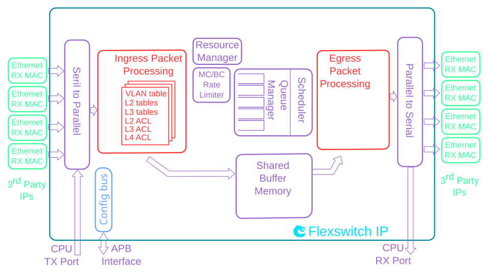
This L2 Ethernet Switch IP Core offers a full range of features with full wirespeed on all ports plus a high speed CPU port.
The IP is compatible with ASIC technology as well as FPGA technology from most vendors.
Each port has priority queues which are controlled by a strict priority scheduler allowing the most timing critical packets to get minimal delay while providing a fairness between queues.
The switching core is built around a shared buffer memory architecture allowing head-of-line-blocking-free switching on all ports operating at wire-speed. It offers dynamic per port and per priority usage of the packet buffer memory along with buffer limiters to limit how much an egress port / priority uses of total buffer memory.
The switching core also features multiple VLAN tagging and un-tagging along with egress VLAN translation.
The L2 Ethernet Switching IP features a processor interface allowing setup of tables and register. It also features a packet based CPU port which can be used to both send and receive ethernet frames to/from the switching IP.
This IP requires no software setup to be used, it is ready to receive and forward Ethernet frames once downloaded to FPGA and connected to MACs. It has hardware learning for MAC addresses.
Detailed Feature List
- 5 x 100 Mbit/s Ethernet ports.
- Full wire-speed on all ports and all Ethernet frame sizes.
- Store and forward shared memory architecture.
- Support for jumbo packets up to 4087 bytes.
- Passes maximum overlap mesh test (RFC2899) excluding the CPU port, for all packet sizes up to 1518 bytes.
- Queue management operations:
- Disable scheduling of packets on a port.
- Disable queuing new packets to a port.
- Allow a port to be drained without sending out packets.
- Allow checking if a port is empty or not.
- Input and output mirroring.
- 4,096 entry L2 MAC table, hash based 4-way.
- 16 entry VLAN table.
- 16 entry synthesized CAM to solve hash collisions.
- 4 entries of the synthesized CAM are fully maskable.
- 128 entry L2 multicast table.
- Automatic aging and wire-speed learning of L2 addresses. Does not require any CPU/software intervention.
- Spanning tree support, ingress and egress checks.
- L2 classification rules. Consists of Source Port, DA MAC, SA MAC, the packets VLAN VID field, the packets VLAN PCP field, the packets VLAN CFI field, Ethernet type.
- 1310720 bits shared packet buffer memory for all ports divided into 2048 cells each of 80 bytes size
- 4 priority queues per egress port.
- Configurable mapping of egress queue from IP TOS, MPLS exp/tc or VLAN PCP bits.
- Deficit Weighted Round Robin Scheduler.
- Egress queue resource limiter with four sets of configurations.
- Configuration interface for accessing configuration and status registers/tables.
- Multicast/Broadcast storm control with separate token buckets for flooding, broadcast and multicast packets.
- Multicast/Broadcast storm control is either packet or byte-based, configurable per egress port.
- LLDP frames can optionally be sent to the CPU.
Deliverables
- Unencrypted Verilog source code of IP.
- Datasheet of registers & theory of operations.
- C source code for accessing registers.
- Easy to parse YML file for register mapping.
- Verilog testbench.
- Low-level device driver.
Datasheet
A datasheet of this example design is available here.

Implementation
| Ports | Altera | Xilinx |
|---|---|---|
| 4x1G | 37k ALMs | 43k LUTs |
| 16x1G | 65k ALMs | 103k LUTs |
| 4x10G | 37k ALMs | 45k LUTs |
| 16x10G | 87k ALMs | 128k LUTs |
Ethernet Switch Advanced L2/VLAN 48x1G + 5x10G
This L2 Ethernet Switch IP Core offers a full range of features with full wirespeed on all ports plus a high speed CPU port.
The IP is compatible with ASIC technology as well as FPGA technology from most vendors.
Each port has priority queues which are controlled by a strict priority scheduler allowing the most timing critical packets to get minimal delay while providing a fairness between queues.
The switching core is built around a shared buffer memory architecture allowing head-of-line-blocking-free switching on all ports operating at wire-speed. It offers dynamic per port and per priority usage of the packet buffer memory along with buffer limiters to limit how much an egress port / priority uses of total buffer memory.
The switching core also features multiple VLAN tagging and un-tagging along with egress VLAN translation.
The L2 Ethernet Switching IP features a processor interface allowing setup of tables and register. It also features a packet based CPU port which can be used to both send and receive ethernet frames to/from the switching IP.
This IP requires no software setup to be used, it is ready to receive and forward Ethernet frames once downloaded to FPGA and connected to MACs. It has hardware learning for MAC addresses.
Detailed Feature List
- 48 ports of 1 Gigabit Ethernet.
- 5 ports of 10 Gigabit Ethernet.
- Full wire-speed on all ports and all Ethernet frame sizes.
- Store and forward shared memory architecture.
- Support for jumbo packets up to 16359 bytes.
- Passes maximum overlap mesh test (RFC2899) excluding the CPU port, for all packet sizes up to 1601 bytes.
- Input and output mirroring.
- RSPAN - Remote Switch Port Analyzer
- 8 source MAC address ranges with a number of different actions.
- 8 destination MAC address ranges with a number of different actions.
- 32,768 entry L2 MAC table, hash based 8-way.
- 4,096 entry VLAN table.
- 64 entry synthesized CAM to solve hash collisions.
- 8 entries of the synthesized CAM are fully maskable.
- 1,024 entry L2 multicast table.
- Automatic aging and wire-speed learning of L2 addresses. Does not require any CPU/software intervention.
- Spanning tree support, ingress and egress checks.
- 64 multiple spanning trees, ingress and egress checks.
- Egress VLAN translation table allowing unique VID-to-VID translation per egress port.
- VLAN priority tag can bypass VLAN processing and be popped on egress.
- Support for masking all look-up keys for L2 MAC table.
- 4432 entries of ingress classification / ACL Lookups. The classification / ACL keys are configurable for each source port and the fields are selected from a incoming packets L2, L3 or L4 fields. The selection is described in 11.2 The classificaiton / ACL key can be up to 322 bits long. The classification / ACL lookup is based on a combination of hash and TCAM. The actions which can be done is listed below:
- Multiple actions can be assigned to each result. All results can be done in parallel if the user so wishes.
- Result action can be to drop a packet.
- Result action can be to send a packet to the CPU port.
- Result action can be to send a packet to a specific port.
- Result action can be to update a counter. There are 256 counters which can be used by the classification / ACL engine.
- Result action can be to force packet to a specific queue on a egress port.
- Result action can be to assign a meter/market/policer to measure the packet bandwidth.
- Result action can be to assign a color to the packet which is used by the meter/marker/policer.
- Result action can be to force the packet to use a specific VID when doing the VLAN table lookup.
- Result action can be to do a input mirror on a packet.
- Result action can be to not allow the packet to be learned in L2 MAC table.
- The ingress configurable classification / ACL engine can use the type and code fields from ICMP frames.
- The ingress configurable classification / ACL engine can use the fields, including the group address, from IGMP frames.
- 17236480 bits shared packet buffer memory for all ports divided into 13466 cells each of 160 bytes size
- 8 priority queues per egress port.
- Configurable mapping of egress queue from IP TOS, MPLS exp/tc or VLAN PCP bits.
- 128 ingress admission control entries.
- Deficit Weighted Round Robin Scheduler.
- Bandwidth shapers per port.
- Individual bandwidth shapers for each priority on each port.
- Individual bandwidth shapers for each queue on each port.
- Egress queue resource limiter with 27 sets of configurations.
- Configuration interface for accessing configuration and status registers/tables.
- Multicast/Broadcast storm control with separate token buckets for flooding, broadcast and multicast packets.
- Multicast/Broadcast storm control is either packet or byte-based, configurable per egress port.
- LLDP frames can optionally be sent to the CPU.
- Attack prevention by TCP flag rules combined with TCP-port and IP address checks, this also includes IMCP length attack checks.
- IEEE 1588 / PTP support for 1-step and 2-step Ordinary Clock mode. The switch supports transfer of 8 byte timestamp from receive MAC to software and form software to transmit MAC.
- Queue management operations:
- Disable scheduling of packets on a port.
- Disable queuing new packets to a port.
- Allow a port to be drained without sending out packets.
- Allow checking if a port is empty or not.
Deliverables
- Unencrypted Verilog source code of IP.
- Datasheet of registers & theory of operations.
- C source code for accessing registers.
- Easy to parse YML file for register mapping.
- Verilog testbench.
- Low-level device driver.
Datasheet
A datasheet of this example design is available here.

Ethernet Switch/Router L2/L3/MPLS 12x10G
This L3 Ethernet Switch/Router IP core is built around a shared buffer memory architecture providing wire-speed switching and routing on all ports without head of line blocking. It offers dynamic allocation of packet buffers per port and priority to avoid starvation due to over-allocation. Advanced QoS features allow the most timing critical packets to get minimal delay while providing fairness between traffic classes.
No initial software setup is required and due to the hardware learning for MAC addresses the core is ready to receive and forward Ethernet frames immediately once powered up. There is a high performance processor interface for register configuration, and a high performance dedicated CPU port for slow path processing of packets.
The design is optimized for both FPGA and ASIC technology but does not have any dependencies on the underlying technology. If the target technology has TCAMs these can be utilized.
Detailed Feature List
- 12 ports of 10 Gigabit Ethernet.
- Full wire-speed on all ports and all Ethernet frame sizes.
- Store and forward shared memory architecture.
- Support for jumbo packets up to 16367 bytes.
- Passes maximum overlap mesh test (RFC2899) excluding the CPU port, for all packet sizes up to 1601 bytes.
- Queue management operations:
- Disable scheduling of packets on a port.
- Disable queuing new packets to a port.
- Allow a port to be drained without sending out packets.
- Allow checking if a port is empty or not.
- Input and output mirroring.
- 4 source MAC address ranges with a number of different actions.
- 4 destination MAC address ranges with a number of different actions.
- 4,096 entry L2 MAC table, hash based 4-way.
- 4,096 entry VLAN table.
- 16 entry synthesized CAM to solve hash collisions.
- 4 entries of the synthesized CAM are fully maskable.
- 64 entry L2 multicast table.
- Automatic aging and wire-speed learning of L2 addresses. Does not require any CPU/software intervention.
- Spanning tree support, ingress and egress checks.
- 16 multiple spanning trees, ingress and egress checks.
- VLAN priority tag can bypass VLAN processing and be popped on egress.
- MPLS forwarding with support for swap,push,pop and penultimate pop operations.
- 4 entry VRF table.
- 1,024 * 4 hash based L3 routing table.
- 16 entry L3 routing TCAM.
- 1,024 entry next hop table. Pointed to from the routing entries.
- 1,024 entry packet modification table used by the next hop table to determine how build l2 fields in a packet to find the next hop.
- Configurable ECMP support based on L3 protocol field,L3 Tos, and L4 SP/DP.
- ECMP supports with up to 256 paths.
- L2 classification rules. Consists of Source Port, DA MAC, SA MAC, the packets VLAN VID field, the packets VLAN PCP field, the packets VLAN CFI field, Ethernet type.
- 32 entry of classification / ACL consist of source port, routed flag, VRF IPv4 packet type, IPv6 packet type, MPLS packet type, source IP address, destination IP address, TOS, L4 type, L4 source port, L4 destination port, TCP flags.
- Support for allowing L2 and L3 classification rules to be combined to larger than 5 tuple lookups.
- 5242880 bits shared packet buffer memory for all ports divided into 4096 cells each of 160 bytes size
- 8 priority queues per egress port.
- Configurable mapping of egress queue from IP TOS, MPLS exp/tc or VLAN PCP bits.
- 16 ingress admission control entries.
- Strict Priority Scheduler.
- Egress queue resource limiter with four sets of configurations.
- Configuration interface for accessing configuration and status registers/tables.
- Multicast/Broadcast storm control with separate token buckets for flooding, broadcast and multicast packets.
- Multicast/Broadcast storm control is either packet or byte-based, configurable per egress port.
- LLDP frames can optionally be sent to the CPU
Datasheet
A datasheet of this example design is available here.

Ethernet Switch/Router Enterprise 9x10G + 2x25G
Detailed Feature List
- 9 ports of 10 Gigabit Ethernet.
- 2 ports of 25 Gigabit Ethernet.
- Full wire-speed on all ports and all Ethernet frame sizes.
- Store and forward shared memory architecture.
- Support for jumbo packets up to 32739 bytes.
- Passes maximum overlap mesh test (RFC2899) excluding the CPU port, for all packet sizes up to 1601 bytes.
- Queue management operations:
- Disable scheduling of packets on a port.
- Disable queuing new packets to a port.
- Allow a port to be drained without sending out packets.
- Allow checking if a port is empty or not.
- Input and output mirroring.
- 4 source MAC address ranges with a number of different actions.
- 4 destination MAC address ranges with a number of different actions.
- 4,096 entry L2 MAC table, hash based 4-way.
- 4,096 entry VLAN table.
- 32 entry synthesized CAM to solve hash collisions.
- 4 entries of the synthesized CAM are fully maskable.
- 64 entry L2 multicast table.
- Automatic aging and wire-speed learning of L2 addresses. Does not require any CPU/software intervention.
- Spanning tree support, ingress and egress checks.
- 16 multiple spanning trees, ingress and egress checks.
- Allows software to inject special packets which are used to write into MAC tables while hardware learning engine is running.
- Allows software to track which L2 MAC entries are being learned and port moved.
- Allows software to track which L2 MAC entries are being aged out.
- Egress VLAN translation table allowing unique VID-to-VID translation per egress port.
- VLAN priority tag can bypass VLAN processing and be popped on egress.
- MPLS forwarding with support for swap,push,pop and penultimate pop operations.
- 4 entry VRF table.
- 512 * 4 hash based L3 routing table.
- 16 entry L3 routing TCAM.
- 1,024 entry next hop table. Pointed to from the routing entries.
- 1,024 entry packet modification table used by the next hop table to determine how build l2 fields in a packet to find the next hop.
- Configurable ECMP support based on L3 protocol field,L3 Tos, and L4 SP/DP. ECMP supports with up to 64 paths.
- 2,048 number of Ingress Network Address Translation (NAT) entries.
- 1,024 number of Egress Network Address Translation (NAT) entries.
- 2504 entries of ingress classification / ACL Lookups. The classification / ACL keys are configurable for each source port and the fields are selected from a incoming packets L2, L3 or L4 fields. The selection is described in 14.2 The classificaiton / ACL key can be up to 540 bits long. The classification / ACL lookup is based on a combination of hash and TCAM. The actions which can be done is listed below:
- Multiple actions can be assigned to each result. All results can be done in parallel if the user so wishes.
- Result action can be to drop a packet.
- Result action can be to send a packet to the CPU port.
- Result action can be to send a packet to a specific port.
- Result action can be to update a counter. There are 64 counters which can be used by the classification / ACL engine.
- Result action can be to force packet to a specific queue on a egress port.
- Result action can be to assign a meter/market/policer to measure the packet bandwidth.
- Result action can be to assign a color to the packet which is used by the meter/marker/policer.
- Result action can be to force the packet to use a specific VID when doing the VLAN table lookup.
- Result action can be to do a input mirror on a packet.
- Result action can be to not allow the packet to be learned in L2 MAC table.
- The ingress configurable classification / ACL engine can use the type and code fields from ICMP frames.
- The ingress configurable classification / ACL engine can use the fields, including the group address, from IGMP frames. 1312 entries of egress classification / ACL rules. The classification / ACL keys are configurable based on what forwarding actions has been done and the fields are selected from the incoming packets L2, L3 or L4 fields and from forwarding results. The selection is described in 14.4 The ACL key can be up to 540 bits long. For each field there are options to only select part of the bits in a field. The ACL lookup is based on a combination of hash and TCAM. The actions are listed below:
- Multiple actions can be assigned to each result. All results can be done in parallel if the user so wishes.
- Result action can be to drop a packet.
- Result action can be to send a packet to the CPU port.
- Result action can be to send a packet to a different port than ingress forwarding has decided.
- Result action can be to update a counter. There are 64 counters which can be used by the classification / ACL engine.
- The egress configurable classification / ACL engine can use the type and code fields from ICMP frames.
- The egress configurable classification / ACL engine can use the fields, including the group address, from IGMP frames.
- 1572864 bits shared packet buffer memory for all ports divided into 1024 cells each of 192 bytes size
- 8 priority queues per egress port.
- Configurable mapping of egress queue from IP TOS, MPLS exp/tc or VLAN PCP bits.
- 32 ingress admission control entries.
- Deficit Weighted Round Robin Scheduler.
- Bandwidth shapers per port.
- Individual bandwidth shapers for each priority on each port.
- Individual bandwidth shapers for each queue on each port.
- Egress queue resource limiter/guarantee with four sets of configurations.
- Configuration interface for accessing configuration and status registers/tables.
- Multicast/Broadcast storm control with separate token buckets for flooding, broadcast and multicast packets.
- Multicast/Broadcast storm control is either packet or byte-based, configurable per egress port.
- LLDP frames can optionally be sent to the CPU.
- IEEE 1588 / PTP support for 1-step and 2-step Ordinary Clock mode. The switch supports transfer of 8 byte timestamp from receive MAC to software and form software to transmit MAC.
- The packets which are sent to the CPU can contain extra sw-defined “meta-data” which software sets up. Meta-data is 2 bytes and can come from a number of different tables.
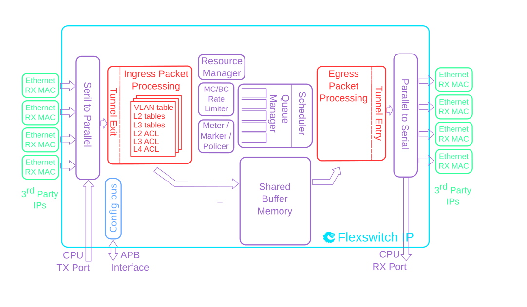
- Wirespeed tunnel exit and tunnel entry. No looping of packets is needed.
- Tunnel unit for both tunnel entry and tunnel exit. Tunnel exit can be done in the beginning of the packet processing or after normal L2, L3, ACL lookups. The tunnel exit can be done on known fields or by looking up bytes anywhere in the first cell of the packet. Tunnel entry can be done as a result from the normal L2,L3, ACL processing.
- The tunnel exit allows packet headers/bytes to removed and certain information to be copied from the original packet to new tunnel exited packet. Once a tunnel exit has been done the new tunnel exited packet will be processed as normal packet at wirespeed.
- The tunnel entry allows packet headers/bytes to be added and certain information from the previous packet to be copied to the new tunnel headers. The tunnel entry is reached from normal L2,L3 and ACL processing and happens just before the packet is sent out allowing the inner packet to do full switching and routing.
Datasheet
A datasheet of this example design is available here.

Ethernet Switch/Router Datacenter ToR 32x100G
Detailed Feature List
- 32 x 100 Gigabit Ethernet ports.
- Full wire-speed on all ports and all Ethernet frame sizes.
- Store and forward shared memory architecture.
- Support for jumbo packets up to 32738 bytes.
- Passes maximum overlap mesh test (RFC2899) using all ports for all packet sizes up to 1601 bytes.
- Queue management operations:
- Disable scheduling of packets on a port.
- Disable queuing new packets to a port.
- Allow a port to be drained without sending out packets.
- Allow checking if a port is empty or not.
- Input and output mirroring.
- 4 source MAC address ranges with a number of different actions.
- 4 destination MAC address ranges with a number of different actions.
- 4,096 entry L2 MAC table, hash based 4-way.
- 4,096 entry VLAN table.
- 32 entry synthesized CAM to solve hash collisions.
- 4 entries of the synthesized CAM are fully maskable.
- 64 entry L2 multicast table.
- Automatic aging and wire-speed learning of L2 addresses. Does not require any CPU/software intervention.
- Spanning tree support, ingress and egress checks.
- 16 multiple spanning trees, ingress and egress checks.
- Allows software to inject special packets which are used to write into MAC tables while hardware learning engine is running.
- Allows software to track which L2 MAC entries are being learned and port moved.
- Allows software to track which L2 MAC entries are being aged out.
- Egress VLAN translation table allowing unique VID-to-VID translation per egress port.
- VLAN priority tag can bypass VLAN processing and be popped on egress.
- MPLS forwarding with support for swap,push,pop and penultimate pop operations.
- 4 entry VRF table.
- 512 * 4 hash based L3 routing table.
- 16 entry L3 routing TCAM.
- 1,024 entry next hop table. Pointed to from the routing entries.
- 1,024 entry packet modification table used by the next hop table to determine how build l2 fields in a packet to find the next hop.
- Configurable ECMP support based on L3 protocol field,L3 Tos, and L4 SP/DP.
- ECMP supports with up to 64 paths.
- 2,048 number of Ingress Network Address Translation (NAT) entries.
- 1,024 number of Egress Network Address Translation (NAT) entries.
- 2504 entries of ingress classification / ACL Lookups. The classification / ACL keys are configurable for each source port and the fields are selected from a incoming packets L2, L3 or L4 fields. The selection is described in 14.2 The classificaiton / ACL key can be up to 540 bits long. The classification / ACL lookup is based on a combination of hash and TCAM. The actions which can be done is listed below:
- Multiple actions can be assigned to each result. All results can be done in parallel if the user so wishes.
- Result action can be to drop a packet.
- Result action can be to send a packet to the CPU port.
- Result action can be to send a packet to a specific port.
- Result action can be to update a counter. There are 64 counters which can be used by the classification / ACL engine.
- Result action can be to force packet to a specific queue on a egress port.
- Result action can be to assign a meter/market/policer to measure the packet bandwidth.
- Result action can be to assign a color to the packet which is used by the meter/marker/policer.
- Result action can be to force the packet to use a specific VID when doing the VLAN table lookup.
- Result action can be to do a input mirror on a packet.
- Result action can be to not allow the packet to be learned in L2 MAC table.
- The ingress configurable classification / ACL engine can use the type and code fields from ICMP frames.
- The ingress configurable classification / ACL engine can use the fields, including the group address, from IGMP frames.
- 1312 entries of egress classification / ACL rules. The classification / ACL keys are configurable based on what forwarding actions has been done and the fields are selected from the incoming packets L2, L3 or L4 fields and from forwarding results. The selection is described in 14.4 The ACL key can be up to 540 bits long. For each field there are options to only select part of the bits in a field. The ACL lookup is based on a combination of hash and TCAM. The actions are listed below:
- Multiple actions can be assigned to each result. All results can be done in parallel if the user so wishes.
- Result action can be to drop a packet.
- Result action can be to send a packet to the CPU port.
- Result action can be to send a packet to a different port than ingress forwarding has decided.
- Result action can be to update a counter. There are 64 counters which can be used by the classification / ACL engine.
- The egress configurable classification / ACL engine can use the type and code fields from ICMP frames.
- The egress configurable classification / ACL engine can use the fields, including the group address, from IGMP frames.
- 33587200 bits shared packet buffer memory divided between 4 switch slices. Each slice holds 4100 cells with a cell size of 256 bytes.
- 8 priority queues per egress port.
- Configurable mapping of egress queue from IP TOS, MPLS exp/tc or VLAN PCP bits.
- 32 ingress admission control entries.
- Deficit Weighted Round Robin Scheduler.
- Bandwidth shapers per port.
- Individual bandwidth shapers for each priority on each port.
- Individual bandwidth shapers for each queue on each port.
- Egress queue resource limiter/guarantee with four sets of configurations.
- Configuration interface for accessing configuration and status registers/tables.
- Multicast/Broadcast storm control with separate token buckets for flooding, broadcast and multicast packets.
- Multicast/Broadcast storm control is either packet or byte-based, configurable per egress port.
- LLDP frames can optionally be sent to the CPU.
- IEEE 1588 / PTP support for 1-step and 2-step Ordinary Clock mode. The switch supports transfer of 8 byte timestamp from receive MAC to software and form software to transmit MAC.
- The packets which are sent to the CPU can contain extra sw-defined “meta-data” which software sets up. Meta-data is 2 bytes and can come from a number of different tables.
- Wirespeed tunnel exit and tunnel entry. No looping of packets is needed.
- Tunnel unit for both tunnel entry and tunnel exit. Tunnel exit can be done in the beginning of the packet processing or after normal L2, L3, ACL lookups. The tunnel exit can be done on known fields or by looking up bytes anywhere in the first cell of the packet. Tunnel entry can be done as a result from the normal L2,L3, ACL processing.
- The tunnel exit allows packet headers/bytes to removed and certain information to be copied from the original packet to new tunnel exited packet. Once a tunnel exit has been done the new tunnel exited packet will be processed as normal packet at wirespeed.
- The tunnel entry allows packet headers/bytes to be added and certain information from the previous packet to be copied to the new tunnel headers. The tunnel entry is reached from normal L2,L3 and ACL processing and happens just before the packet is sent out allowing the inner packet to do full switching and routing.
Datasheet
A datasheet of this example design is available here.

Ethernet Switch/Router IPSec/MACSec 9x10G + 2x40G
Detailed Feature List
- 9 ports of 10 Gigabit Ethernet.
- 2 ports of 40 Gigabit Ethernet.
- Full wire-speed on all ports and all Ethernet frame sizes.
- Store and forward shared memory architecture.
- Support for jumbo packets up to 32733 bytes.
- Passes maximum overlap mesh test (RFC2899) excluding the CPU port, for all packet sizes up to 1601 bytes.
- Queue management operations:
- Disable scheduling of packets on a port.
- Disable queuing new packets to a port.
- Allow a port to be drained without sending out packets.
- Allow checking if a port is empty or not.
- Input and output mirroring.
- 4 source MAC address ranges with a number of different actions.
- 4 destination MAC address ranges with a number of different actions.
- 16,384 entry L2 MAC table, hash based 8-way.
- 4,096 entry VLAN table.
- 32 entry synthesized CAM to solve hash collisions.
- 4 entries of the synthesized CAM are fully maskable.
- 512 entry L2 multicast table.
- Automatic aging and wire-speed learning of L2 addresses. Does not require any CPU/software intervention.
- Spanning tree support, ingress and egress checks.
- 16 multiple spanning trees, ingress and egress checks.
- Allows software to inject special packets which are used to write into MAC tables while hardware learning engine is running.
- Allows software to track which L2 MAC entries are being learned and port moved.
- Allows software to track which L2 MAC entries are being aged out.
- Egress VLAN translation table allowing unique VID-to-VID translation per egress port.
- VLAN priority tag can bypass VLAN processing and be popped on egress.
- MPLS forwarding with support for swap,push,pop and penultimate pop operations.
- 4 entry VRF table.
- 16,384 * 4 hash based L3 routing table.
- 32 entry L3 routing TCAM.
- 2,048 entry next hop table. Pointed to from the routing entries.
- 2,048 entry packet modification table used by the next hop table to determine how build l2 fields in a packet to find the next hop.
- Configurable ECMP support based on L3 protocol field,L3 Tos, and L4 SP/DP
- ECMP supports with up to 64 paths.
- 8,192 number of Ingress Network Address Translation (NAT) entries.
- 8,192 number of Egress Network Address Translation (NAT) entries.
- 10184 entries of ingress classification / ACL Lookups. The classification / ACL keys are configurable for each source port and the fields are selected from a incoming packets L2, L3 or L4 fields. The selection is described in 15.2 The classificaiton / ACL key can be up to 560 bits long. The classification / ACL lookup is based on a combination of hash and TCAM. The actions which can be done is listed below:
- Multiple actions can be assigned to each result. All results can be done in parallel if the user so wishes.
- Result action can be to drop a packet.
- Result action can be to send a packet to the CPU port.
- Result action can be to send a packet to a specific port.
- Result action can be to update a counter. There are 64 counters which can be used by the classification / ACL engine.
- Result action can be to force packet to a specific queue on a egress port.
- Result action can be to assign a meter/market/policer to measure the packet bandwidth.
- Result action can be to assign a color to the packet which is used by the meter/marker/policer.
- Result action can be to force the packet to use a specific VID when doing the VLAN table lookup.
- Result action can be to do a input mirror on a packet.
- Result action can be to not allow the packet to be learned in L2 MAC table.
- The ingress configurable classification / ACL engine can use the type and code fields from ICMP frames.
- The ingress configurable classification / ACL engine can use the fields, including the group address, from IGMP frames.
- 9232 entries of egress classification / ACL rules. The classification / ACL keys are configurable based on what forwarding actions has been done and the fields are selected from the incoming packets L2, L3 or L4 fields and from forwarding results. The selection is described in 15.4 The ACL key can be up to 135 bits long. For each field there are options to only select part of the bits in a field. The ACL lookup is based on a combination of hash and TCAM. The actions are listed below:
- Multiple actions can be assigned to each result. All results can be done in parallel if the user so wishes.
- Result action can be to drop a packet.
- Result action can be to send a packet to the CPU port.
- Result action can be to update a counter. There are 64 counters which can be used by the classification / ACL engine.
- Result action can be to force packet to a specific queue on a egress port.
- The egress configurable classification / ACL engine can use the type and code fields from ICMP frames.
- The egress configurable classification / ACL engine can use the fields, including the group address, from IGMP frames.
- 1572864 bits shared packet buffer memory for all ports divided into 1024 cells each of 192 bytes size
- 8 priority queues per egress port.
- Configurable mapping of egress queue from IP TOS, MPLS exp/tc or VLAN PCP bits.
- 64 ingress admission control entries.
- Deficit Weighted Round Robin Scheduler.
- Bandwidth shapers per port.
- Individual bandwidth shapers for each priority on each port.
- Individual bandwidth shapers for each queue on each port.
- Egress queue resource limiter/guarantee with four sets of configurations.
- Configuration interface for accessing configuration and status registers/tables.
- Multicast/Broadcast storm control with separate token buckets for flooding, broadcast and multicast packets.
- Multicast/Broadcast storm control is either packet or byte-based, configurable per egress port.
- LLDP frames can optionally be sent to the CPU.
- IEEE 1588 / PTP support for 1-step and 2-step Ordinary Clock mode. The switch supports transfer of 8 byte timestamp from receive MAC to software and form software to transmit MAC.
- The packets which are sent to the CPU can contain extra sw-defined “meta-data” which software sets up. Meta-data is 2 bytes and can come from a number of different tables.
- Wirespeed tunnel exit and tunnel entry. No looping of packets is needed.
- Tunnel unit for both tunnel entry and tunnel exit. Tunnel exit can be done in the beginning of the packet processing or after normal L2, L3, ACL lookups. The tunnel exit can be done on known fields or by looking up bytes anywhere in the first cell of the packet. Tunnel entry can be done as a result from the normal L2,L3, ACL processing.
- The tunnel exit allows packet headers/bytes to removed and certain information to be copied from the original packet to new tunnel exited packet. Once a tunnel exit has been done the new tunnel exited packet will be processed as normal packet at wirespeed.
- The tunnel entry allows packet headers/bytes to be added and certain information from the previous packet to be copied to the new tunnel headers. The tunnel entry is reached from normal L2,L3 and ACL processing and happens just before the packet is sent out allowing the inner packet to do full switching and routing.
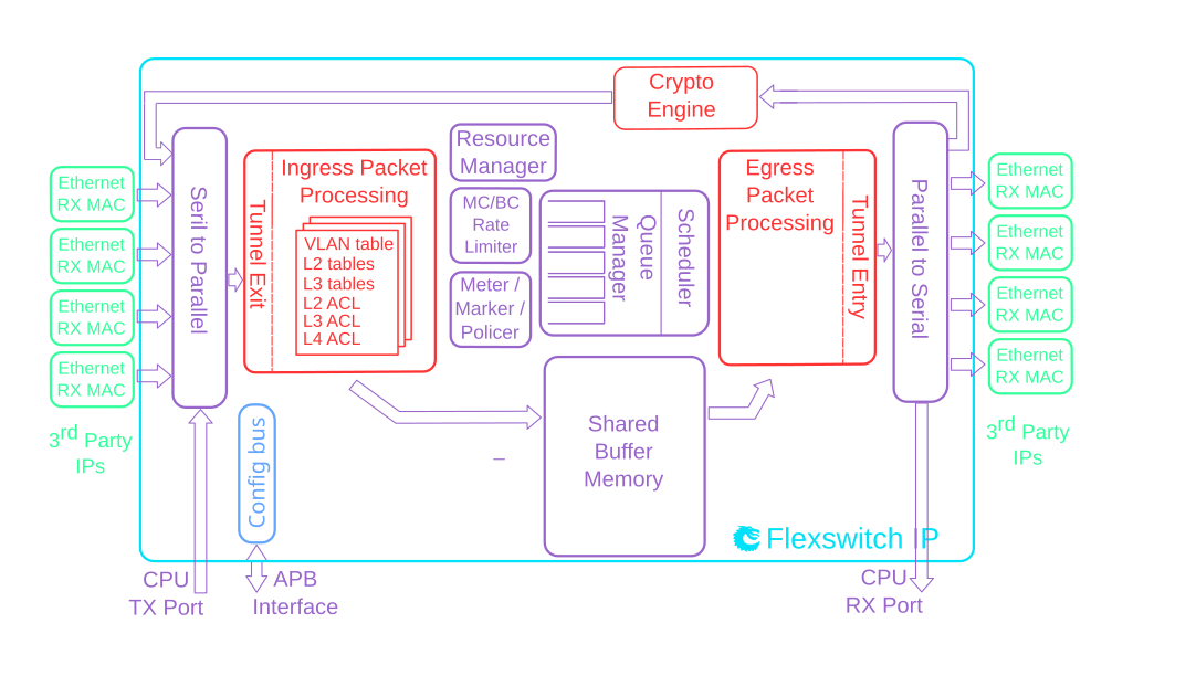
- A crypt unit enables support for IPsec with both AH , ESP and ESP tunneling support. Includes many crypto modes and authentication modes for both encryption, decryption and authentication.
- The core also supports MACsec encryption and decryption. The MACsec support allows VLANs to be located both before and after the MACsec header.
- Table syncronization mechanism using versioning of functionality divided into multiple tables. See chapter 26.
Datasheet
A datasheet of this example design is available here.

Ethernet Switch TSN 7x1G + 2x3G
Detailed Feature List
- 7 ports of 1 Gigabit Ethernet.
- 2 ports of 3 Gigabit Ethernet.
- Full wire-speed on all ports and all Ethernet frame sizes.
- Store and forward shared memory architecture.
- Support for jumbo packets up to 32749 bytes.
- Passes maximum overlap mesh test (RFC2899) using all ports for all packet sizes up to 1518 bytes.
- Time-Sensitive Networking:
- IEEE Std 802.1Qci-2017: Per-Stream Filtering and Policing
- IEEE Std 802.1CB-2017: Frame Replication and Elimination for Reliability
- IEEE Std 802.1Qbv-2015: Enhancements for Scheduled Traffic
- IEEE Std 802.1Qav-2009: Credit Based Shaper
- Queue management operations:
- Disable scheduling of packets on a port.
- Disable queuing new packets to a port.
- Allow a port to be drained without sending out packets.
- Allow checking if a port is empty or not.
- Input and output mirroring.
- RSPAN - Remote Switch Port Analyzer
- 4 source MAC address ranges with a number of different actions.
- 4 destination MAC address ranges with a number of different actions.
- 1,024 entry L2 MAC table, hash based 4-way.
- 4,096 entry VLAN table.
- 16 entry synthesized CAM to solve hash collisions.
- 4 entries of the synthesized CAM are fully maskable.
- 64 entry L2 multicast table.
- Automatic aging and wire-speed learning of L2 addresses. Does not require any CPU/software intervention.
- Spanning tree support, ingress and egress checks.
- 16 multiple spanning trees, ingress and egress checks.
- Egress VLAN translation table allowing unique VID-to-VID translation per egress port.
- VLAN priority tag can bypass VLAN processing and be popped on egress.
- 496 entries of ingress classification / ACL Lookups. The classification / ACL keys are configurable for each source port and the fields are selected from a incoming packets L2, L3 or L4 fields. The selection is described in 10.2 The classificaiton / ACL key can be up to 372 bits long. The classification / ACL lookup is based on a combination of hash and TCAM. The actions which can be done is listed below:
- Multiple actions can be assigned to each result. All results can be done in parallel if the user so wishes.
- Result action can be to drop a packet.
- Result action can be to send a packet to the CPU port.
- Result action can be to send a packet to a specific port.
- Result action can be to update a counter. There are 32 counters which can be used by the classification / ACL engine.
- Result action can be to force packet to a specific queue on a egress port.
- Result action can be to assign a meter/market/policer to measure the packet bandwidth.
- Result action can be to assign a color to the packet which is used by the meter/marker/policer.
- Result action can be to force the packet to use a specific VID when doing the VLAN table lookup.
- Result action can be to do a input mirror on a packet.
- Result action can be to not allow the packet to be learned in L2 MAC table.
- The ingress configurable classification / ACL engine can use the type and code fields from ICMP frames.
- The ingress configurable classification / ACL engine can use the fields, including the group address, from IGMP frames.
- 1843200 bits shared packet buffer memory for all ports divided into 1536 cells each of 150 bytes size
- 8 priority queues per egress port.
- Configurable mapping of egress queue from IP TOS, MPLS exp/tc or VLAN PCP bits.
- 32 ingress admission control entries.
- Deficit Weighted Round Robin Scheduler.
- Bandwidth shapers per port.
- Individual bandwidth shapers for each priority on each port.
- Individual bandwidth shapers for each queue on each port.
- Egress queue resource limiter with four sets of configurations.
- Configuration interface for accessing configuration and status registers/tables.
- Multicast/Broadcast storm control with separate token buckets for flooding, broadcast and multicast packets.
- Multicast/Broadcast storm control is either packet or byte-based, configurable per egress port.
- LLDP frames can optionally be sent to the CPU.
- Attack prevention by TCP flag rules combined with TCP-port and IP address checks, this also includes IMCP length attack checks.
Datasheet
A datasheet of this example design is available here.
News
2024 March
Full steam ahead!
During 2023 we have delivered IP-cores with IPSec, MACSec, NAT and a slew of TSN features. Now in 2024 we are building cores for our largest customer yet, a top tier networking company!
2022 July
First half of 2022
In the first half of 2022 we have had design wins for both new and repeat customers. We keep churning out the IP cores!
2021 December
2021 – A record year!
2021 has been a record year for PacketArc! We have reached new highs both in delivered ASIC and FPGA cores, and in new customer interest. So things are looking good for 2022 as well!
2021 April
ASIC design win!
The first quarter of 2021 saw us deliver the first of five ASIC cores to a new customer! The five cores span a range of bandwidths and feature sets for industrial, Enterprise, SOHO, and automotive applications.
2020 December
Activities second half of 2020
The second half of 2020 was interesting times, seeing us deliver aerospace cores to three new customers! One of the cores had multiple 100G ports in a mid-range FPGA. We also did our first foray into custom protocols, with cores for a high performance wireless chipset.
2020 August
Activities first half of 2020
Late 2019 and the first half of 2020 saw us fully occupied in customer projects, some of which panned out, and others that were torpedoed by the pandemic.
2019 September
Activities in 2019-Q3
This quarter we have focused on timing optimization and hierarchy restructuring to simplify floorplanning and P&R. Therefore there are no new, cool features released this quarter.
2019 June
New IP release 2019-Q2
- Meter / Marker / Policer (MMP) compliant with MEF, DiffServ
- Software C-model of complete switch/router for use in software development, verification or IP evaluation.
- C-API enhanced with functions to simplify accessing hash table entries.
2019 March
New IP release 2019-Q1
- C-software API released
- FPGA based evaluation platform available purchase or loan
- Added support for Achronix and Microsemi FPGAs
- New resource manager with queue guarantees for the packet buffer
- Improved statistics for debugging
- Verilator is now our main simulator
2018 October
PacketArc IP is used to demonstrate multi-threaded
simulation speed-up
The impressive open-source simulator Verilator now in version 4 supports multi-threading. The developer Wilson Snyder needed a large real-world design to benchmark the performance, and we were happy to give him an IP core to play with. And it is looking good! See slides 17 and forward in the presentation from ORConf 2018: Verilator 4.0: Open Simulation Goes Multithreaded
2017 August
Design win: High-performance L3/MPLS router
We are thrilled to announce that in our largest deal to date our IP will be used to produce a high-performance L3/MPLS router ASIC with multiple 100G Ethernet ports!
2016 September
Press release: Cambium Networks chooses
FlexSwitch IP for their PTP 700 platform
Cambium Networks and Packet Architects AB announce that Cambium Networks PTP 700 platform from will use Ethernet switch IP from Packet Architects AB.
2015 March
Elektroniktidningen: Switchar utan dödkött
The Swedish magazine Elektroniktidningen publishes an extensive article about Packet Architects.
2011 November
IDG: Lundabolag flyttar till USA
Swedish magazine covers Packet Architects.
Contact
Packet Architects AB is based in Lund, Sweden.
For further information contact us at:
email: info@packetarc.com
Visiting address:
Ideon Science Park
Scheelevägen 17
SE 223 63 Lund
Sweden
About Us
Packet Architects AB was founded in 2011 by a team with extensive experience in designing ASICs for communication systems.
Having seen the costly development time for these types of systems and the lack of flexibility in existing IP cores led to the founding of Packet Architects and the development of the FlexSwitch tool-chain.
The starting point was a tool-chain that could create customer specific IP cores with very little effort for each new core. The success of this approach has then allowed us to add more and more advanced features.
Today we have customers spanning a very wide range of switching markets from traditional enterprise switches, avionics, experimental networks and even into interplanetary space networks.
The Management Team
Kenny Ranerup – CEO
Kenny Ranerup served as CTO and Director of Engineering at SwitchCore. Research Manager at Axis Communications. Managing Director at Swedish LCD center.
Per Karlsson – Chief Architect
Per Karlsson is an expert in micro-architecture, power management and physical implementation. He was technical leader for the datapath at SwitchCore, and a technical leader for a succession of Digital Baseband ASICs at Ericsson
Robert Wikander – CTO
Robert Wikander is a switching architecture expert with with experience developing switching systems from a few giga-bit to multi-terabit performance. Before Packet Architects he was chief architect at the networking business unit at Realtek Semiconductor, and Chief ASIC Architect at SwitchCore. He is a lecturer in Ethernet Switch Design at Luleå and Lund Universities